| |
Insulated-Gate Bipolar Transistor (IGBT)
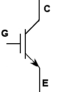
The insulated-gate bipolar transistor (IGBT) is a three-terminal power semiconductor device that merges characteristics of two earlier device families. From the metal-oxide-semiconductor field-effect transistor (MOSFET) it borrows a voltage-controlled insulated gate, so the control terminal draws almost no steady-state current and is easy to drive. From the bipolar junction transistor (BJT) it borrows conductivity modulation in a wide, lightly doped drift region, which gives a low on-state voltage drop even at high current. Its terminals are usually called the gate, collector and emitter.
This combination makes the IGBT well suited to applications that handle large currents at medium to high voltages. A small voltage applied between gate and emitter creates an inversion channel that turns the device on, after which injected charge carriers flood the drift region and reduce its resistance. Compared with a power MOSFET of similar rating, an IGBT typically conducts large currents with a lower forward drop, while compared with a bipolar transistor it is far simpler to switch because the gate is capacitive rather than current-driven.
IGBTs are widely used in motor drives, inverters, switched-mode power supplies, induction heating, uninterruptible power supplies, and traction systems for electric and hybrid vehicles and trains. A practical limitation is switching speed: stored minority charge produces a current “tail” during turn-off, so IGBTs generally switch more slowly than MOSFETs and are most efficient at the lower switching frequencies common in high-power converters. Devices are often packaged as modules combining several IGBTs with anti-parallel freewheeling diodes.
Frequently asked questions
- How does an IGBT differ from a power MOSFET?
- Both use an insulated gate, but the IGBT adds bipolar conduction in its drift region. This lowers the on-state voltage drop at high current, at the cost of slower switching due to stored charge.
- When is an IGBT preferred over a MOSFET?
- IGBTs are generally chosen for higher-voltage, higher-current applications switched at moderate frequencies, such as motor drives and inverters. MOSFETs are favoured at lower voltages and higher switching frequencies.
- What is the current tail in an IGBT?
- When the device turns off, minority carriers stored in the drift region take time to recombine, producing a residual collector current. This tail increases turn-off switching losses.
|
|
IGBT  |
|
Application
Characterization of IGBTs Gate Drive Requirements, Switching Trajectories
and Safe Operating Area Considerations, Conduction Losses, Calculation of
switching losses with an ideal diode, Methods To Calculate Junction Temperature
And Power Dissipation For A Given Operating Condition, Replacing MOSFETs With IGBTs, pdf file |
|
Differences
between MOSFET and IGBT The differences between MOSFET and IGBT |
|
DRIVE
CIRCUITS FOR POWER MOSFETs AND IGBTs Unlike the bipolar transistor, which is
current driven, Power MOSFETs, with their insulated gates, are voltage driven. A
basic knowledge of the principles of driving the gates of these devices will
allow the designer to speed up or slow down the switching speeds according to
the requirements of the application, pdf file |
|
Drivers for power
transistors MOSFET and IGBT drivers for power
transistors MOSFET and IGBT |
|
IGBT pdf file |
|
IGBT en Français |
|
IGBT en Français, pdf file |
| IGBT Power MOSFET and IGBT, n channel-enhancement power
MOSFETs and IGBTs (enhancement transistors, Common switch symbols, IGBT
structures and their electrical field characteristics during offstate, Causes
and designations of the parasitic capacitances and resistances, pdf file |
| IGBT
IGBT (Insulated Gate Bipolar Transistor) basics, pdf file |
| IGBT
IGBT (Insulated Gate Bipolar Transistor) basics, pdf file |
|
IGBT operation pdf file |
| IGBT
basics it has a MOS gate input structure, which has a simple gate control circuit design and is capable of fast switching up to 100kHz. Additionally,
because the IGBT output has a bipolar transistor structure, its current conduction capability is superior to a bipolar power transistor. Based upon
these excellent characteristics, the IGBT has been extensively used in applications exceeding 300V voltage as an alternative to power MOSFETs and
bipolar power transistors, pdf file |
| IGBT
basics 2 Gate Drive Considerations, IGBT switching waveforms, Analysis of
turn-on transient, Gate drive design basics, VGG+, Effect on-state, Effect on
turn-on, Effect on the short circuit capability, Effect on turn-off, RG, Effect
on turn-on, Effect on turn-off, Gate drive power, requirement, Gate drive layout
considerations, Effect of gate line inductance on the induced turn-on, Power
source stabilizing capacitor, Isolation problem, Wiring pattern, Common emitter
problems, Short circuit protection, Protecting against over-current condition,
Protecting against short circuit current condition, Short Circuit Protection
Scheme, Detection through resistance, Current Transformer, De-saturation
detection, pdf file |
|
IGBT characteristics
How The IGBT Complements The Power MOSFET, Silicon Structure And Equivalent
Circuit, Conduction Characteristics, Switching Characteristics, Latching, Safe
Operating Area, Transconductance, How To Read The Data Sheet, The Absolute
Maximum Ratings, Thermal Resistance, Electrical Characteristics, Switching
Characteristics, pdf file |
|
IGBT Driver Application
Note IGBT Driver Calculation, pdf file |
|
IGBT Electrostatic Handling Precautions pdf file |
|
IGBT
- MOSFET driver en Français |
|
IGBT Ratings And
Characteristics The following information attempts to give clear definitions
of the ratings parameters on a typical IGBT datasheet and describes how the
current and power ratings are derived, pdf file |
| IGBT tutorial insulated gate bipolar transistor (IGBT), equivalent circuit, IGBT, pdf file |
| IGBT
or MOSFET? the IGBT has the output switching and conduction characteristics of a bipolar transistor but is
voltage-controlled like a MOSFET. In general, this means it has the advantages of high-current handling capability of a bipolar with the ease of control of a
MOSFET, pdf file |
|
Insulated Gate Bipolar Transistor (IGBT) insulated gate bipolar transistor (IGBT) |
|
Insulated Gate Bipolar Transistor (IGBT) insulated gate bipolar transistor (IGBT), pdf file |
|
Integrated smart power IGBT drivers pdf file |
|
Introduction to Insulated Gate Bipolar Transistors
Cross Section and Equivalent Schematic of an Insulated Gate Bipolar Transistor
(IGBT) Cell, Cross Section and Equivalent Schematic of an Metal Oxide
Semiconductor Field Effect Transistor (MOSFET) Cell, IGBT Schematic Symbol,
MOSFET Schematic Symbol, IGBT Current Turn off Waveform, Advantages Offered by
the IGBT When Comparing the MOSFET, IGBT and Bipolar Transistor On Resistances
(Over Junction Temperature) and Fall Times (Resistance Values at 10 Amps of
Current), pdf file |
|
Parallel Connection of
IGBT & MOSFET Power Modules Several dice are usually connected in
parallel within high current power modules. IGBT and MOSFET modules must then be
paralleled to increase current capability sufficient for systems with several
hundreds of kW of output power, pdf file |
|
Protecting IGBTs and MOSFETs from ESD
ESD is the discharge of static electricity. Static electricity is an excess or
deficiency of electrons on one surface with respect to another surface or to
ground |
|
Teaching System: IGBT Power Electronics |
|
Use Gate Charge
to Design the Gate Drive Circuit for Power MOSFETs and IGBTs Input behavior
of a MOS-gated transistor, Test Circuit, The Gate Charge Curve, pdf file |
|
|
Home
|
Site Map
|
Email: support[at]karadimov.info
Last updated on:
2026-06-24
|
Copyright © 2011-2021 Educypedia.
https://educypedia.org
|
| |
|
|