| |
Transmission Lines
A transmission line is a pair of conductors arranged to carry electrical signals from one point to another while controlling the way the signal propagates. Familiar examples include coaxial cable, twisted pair and parallel-wire (ladder) line. At low frequencies a cable behaves like a simple wire, but as the signal frequency rises and the wavelength becomes comparable to the cable length, the line must be treated as a distributed circuit with capacitance, inductance, resistance and leakage spread along its length.
A central property is the characteristic impedance, the ratio of voltage to current for a wave travelling along the line. It depends on the conductor geometry and on the dielectric material between the conductors, not on the cable length. Common coaxial cables are made to standard impedances such as 50 or 75 ohms. The dielectric also sets the velocity of propagation, the speed at which signals travel relative to the speed of light in free space, which is always less than one because the insulating material slows the wave.
When a line is terminated in a load equal to its characteristic impedance, energy is fully absorbed and no signal is reflected. A mismatch causes part of the wave to reflect back toward the source, producing standing waves and reducing efficiency, so impedance matching is important in radio and high-speed digital work. Real cables also introduce loss that grows with frequency, attenuating the signal over distance. The Smith chart is a graphical tool engineers use to handle impedance and matching calculations on transmission lines.
Frequently asked questions
- What is characteristic impedance?
- It is the ratio of voltage to current for a wave moving along a line, set by the conductor geometry and dielectric. Common coaxial cables are 50 or 75 ohms, independent of length.
- Why does impedance matching matter?
- If the load does not match the line, part of the signal reflects back, creating standing waves and losses. Matching ensures the energy is delivered efficiently to the load.
- What is velocity of propagation?
- It is the speed at which a signal travels along a cable, expressed as a fraction of the speed of light. The dielectric between the conductors slows the wave, so the value is always below one.
|
|
Transmission
lines  related subject: Antennas, Cabling theory,
Electro magnetic waves,
RF transformers,
TDR Measurements,
Waves (physics)
related subject: Antennas, Cabling theory,
Electro magnetic waves,
RF transformers,
TDR Measurements,
Waves (physics) |
| Ligne de transmission
en Français, pdf-file |
|
Transmission lines
finite resistance in transmission lines, proximity effect in transmission lines, a physical phenomenon that
cause opposing currents in adjacent wires to draw toward one another, the
proximity effect is caused by changing magnetic fields and therefore does
not occur for low frequency signals, a tip |
|
Transmission line
and termination Characteristic impedance of a coax cable and twin lead
cable, balun, twisted pair, impedance matching, ppt
file |
|
Transmission lines pdf-file |
|
Transmission lines
The transmitter that generates the RF power to drive the antenna is usually
located at some distance from the antenna terminals. The connecting link between
the two is the RF transmission line. Its purpose is to carry RF power from one
place to another, and to do this as efficiently as possible,
pdf-file |
| Transmission lines
a tip, animated |
|
Transmission
lines pdf-file |
|
Transmission lines ppt file |
| Transmission lines
definitions for transmission lines, microwaves, power flow on transmission
lines, stub tuner matching, the SMITH chart, standing wave patterns, microwave
measurements, scattering parameters and the S-matrix, waveguides and cavity
resonators, microstrip |
| Transmission
lines and antennas wave propagation, sound waves, light waves, electric field, speed of light, polarization, sky wave, ionosphere, refraction,
transmission lines, tropospheric, reflection, terminating, standing waves, characteristic impedance, radiations, folded dipole, radiation resistance |
| Transmission line
transformers balun, Guanella 1:4 balun |
|
Transmission line transformers pdf-file |
|
Transmission lines tutorial explores transmission line behavior,
educypedia |
| Transmission
lines tutorials transmission line tutorials in pdf format,
a tip |
| Transmission line theory pdf-file |
|
Understanding Coaxial RF Transmission Lines by Measurement and Calculation
Page 1 |
|
|
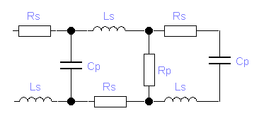
Characteristic impedance calculation:
|
| Twincable (300
W ) |
Coax cable (50, 75, ..
Ohm ) |
-
L = 2.7 µH/m
-
C = 30 pF/m
-
Rs = 0.15
W/m
-
Rp = 1014
W/m
|
-
L = 0.5 µH/m
-
C = 47 pF/m
-
Rs = 0.002
W/m
-
Rp = 1012
W/m
|
|
|
|
|

Coax cable:
|
Zk = 138/√er
. log(D/d) (W)
L = µrµ0/2p
. ln(D/d) (H/m)
C = 2pere0/
ln(D/d) (F/m) |
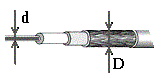
er:
dielectric constant
(relative permittivity) of the medium (if you don't know take 2.3,
Polyethylene), air = 1
e0: permittivity of free
space: 8.8542.10-12 F/m
d : the diameter of the inner conductor
D : the diameter of the outer conductor
µ0: Permeability of a vacuum: 4xp×10-7 H/m
µr:
relative permeability of the medium: air = 1
Twin lead (balanced pair):
|
Zk = 276/√er
. log(2a/d) (W)
L = µrµ0/p
. ln(2a/d) (H/m)
C = pere0/
ln(2a/d) (F/m) |
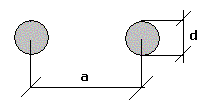
µr: relative permeability of the medium |
|
|
|
|
|
|
|
|
|
|
|
|
|
|
Home
|
Site Map
|
Email: support[at]karadimov.info
Last updated on:
2026-06-24
|
Copyright © 2011-2021 Educypedia.
https://educypedia.org
|
| |
|
|
